How Your Car’s AC Works AutoZone
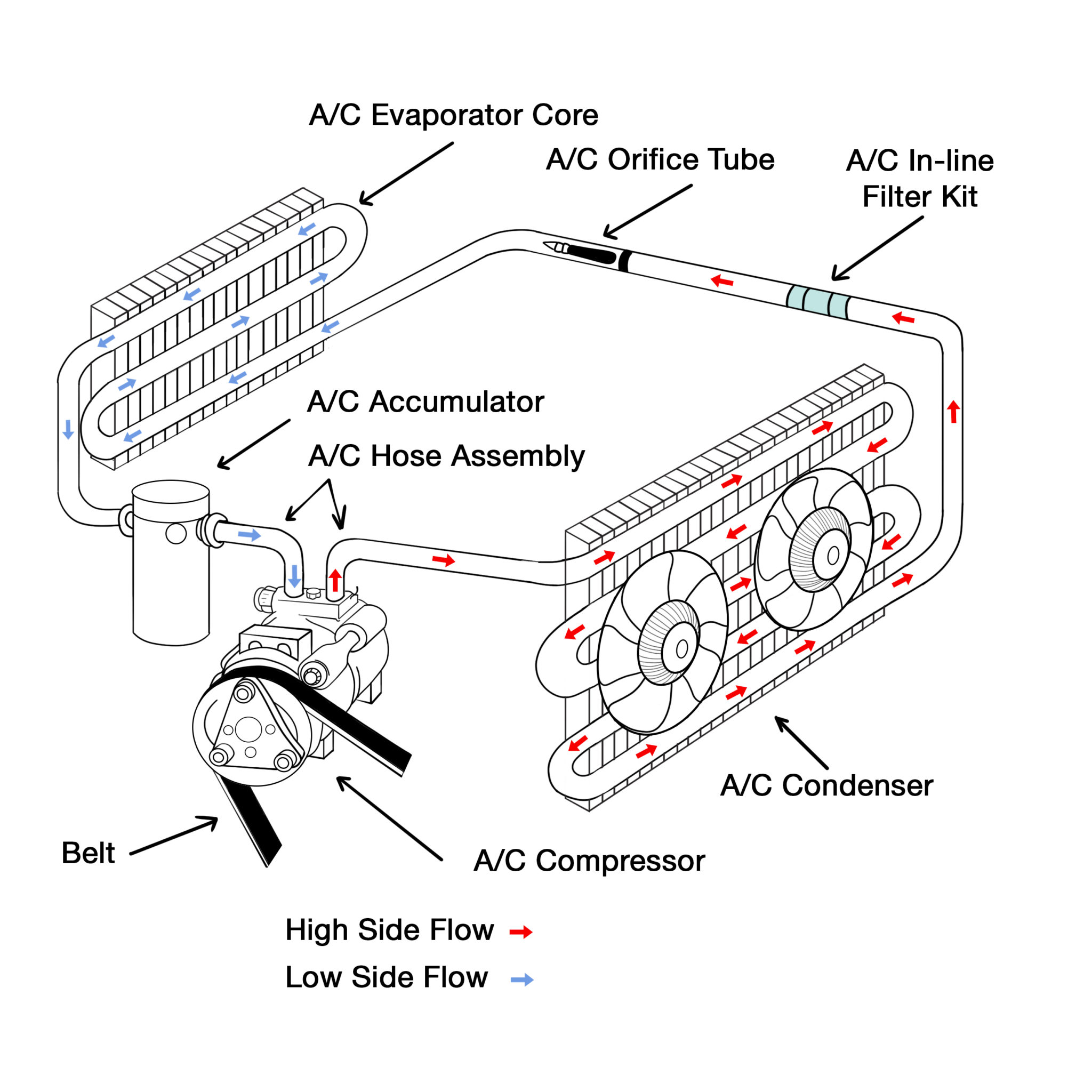
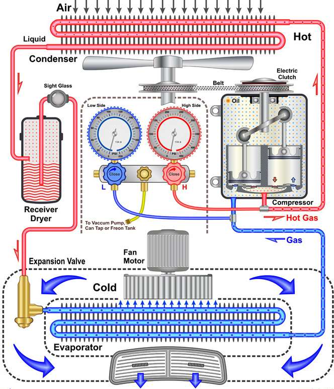
The diagram below shows the entire system and refrigerant flow (high pressure in red, and low pressure in blue). These systems are closed (sealed) which continuously re-circulates the refrigerant. A receiver dryer or an accumulator is used to filter and remove moister from the refrigerant to help prevent the system from being damaged by rust or corrosion.
Automotive Ac System Diagram And Description
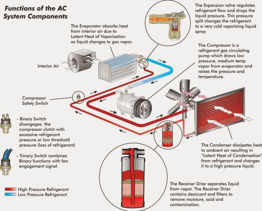
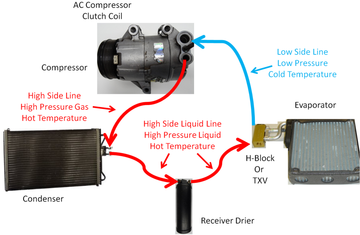
Recharging a Car's AC The High-pressure Side All automotive air conditioning systems are (nearly) closed loops with a high-pressure side and low-pressure side. We'll start with the high-pressure side as it leads from the engine to the passenger compartment: Compressor: The compressor is a pump driven by a belt attached to the engine's crankshaft.
Car Air Conditioning Circuit Diagram
8. Charging - Charge the A/C system with R134a to approx. 90% of the original R12 charge quantity e.g. original R12 1000 grams, R134a retrofit charge 900 grams. Automotive Air Conditioning Training Manual 54 fRetrofitting From refrigerant R12 to R134a 9.

Car Ac Working Diagram Recharging Car Air Conditioning Did It Myself akhiri hidupnya
89K views 4 years ago The 2 main A/C systems explained: Orifice Tube/Accumulator System vs. Expansion Valve/Drier System. SEE MORE AUTOMOTIVE A/C TECH TIPS AT:.
Automotive Ac Diagram
How Does a Car's Air Conditioning Work? Any AC system requires a refrigerant, such as R-134a. Your vehicle's compressor, powered by the serpentine belt, compresses the refrigerant into a liquid, putting it into a high-pressure state.
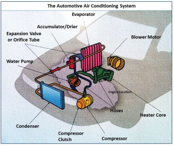
Diagram Of Car Airconditioning Parts
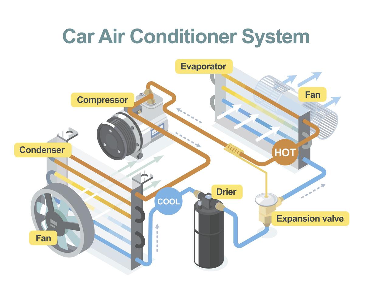
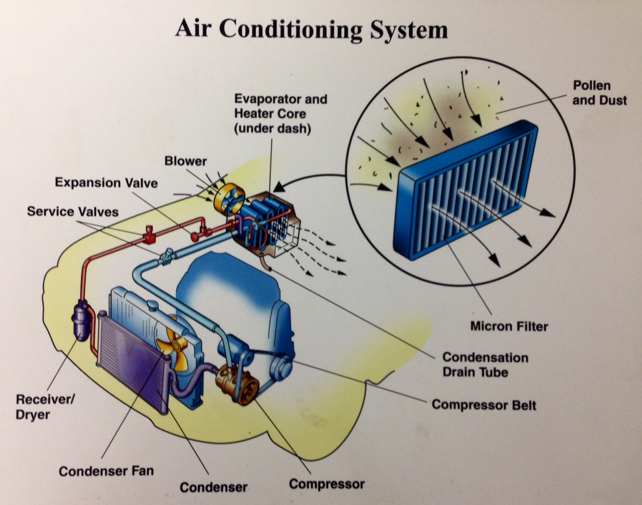
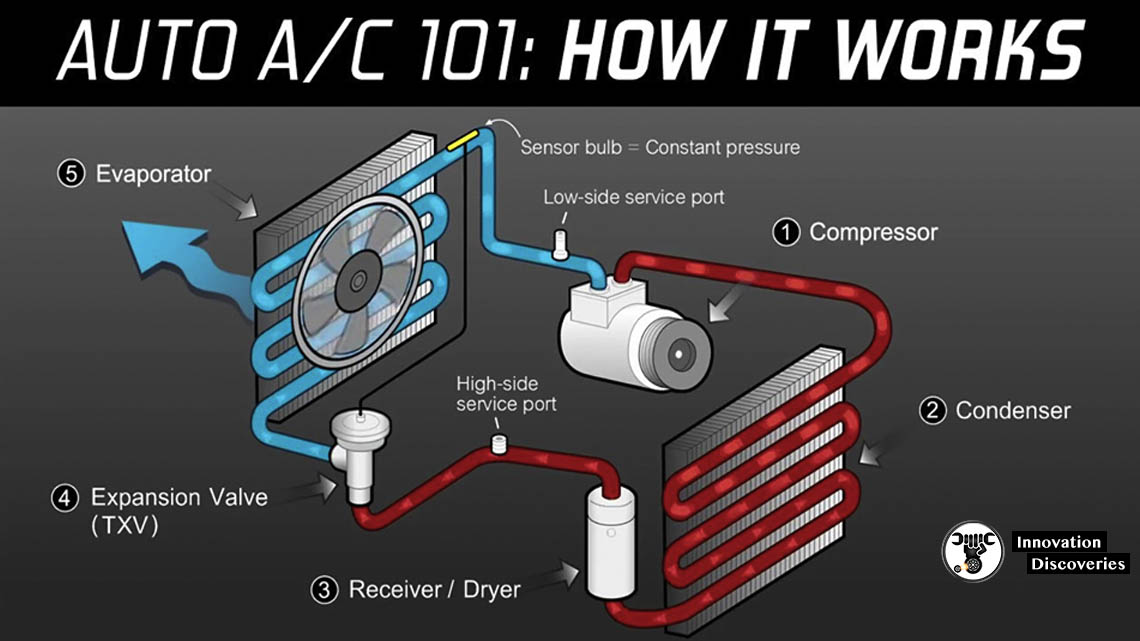
There are five main parts of a car A/C: Compressor Condenser Thermal expansion valve or orifice tube Evaporator Accumulator or receiver/drier Each of the parts is connected by tubing or hoses to form a closed loop. Through that loop runs refrigerant, which is what really does the work of cooling down the air.
20180430135341)
How A/C works in your vintage car Hagerty Media
share alike - If you remix, transform, or build upon the material, you must distribute your contributions under the same or compatible license as the original. Diagram of automotive a/c components. Call Excalibur Auto Repair in Austin TX for fast, expert car and truck A/C repairs.
Car Ac Unit Diagram
Table of Contents Car Air Conditioning AC System | Function , Components , Working The components used in automobile AC are- 1. Compressor - 2. Condenser - 3. Expansion valve- 4. Evaporator - 5. Receiver-Dryer- Receiver/driers serve three very important functions: 6. Refrigerant - 7. Pressure Regulating Devices 8. Orifice Tube 9. Accumulator
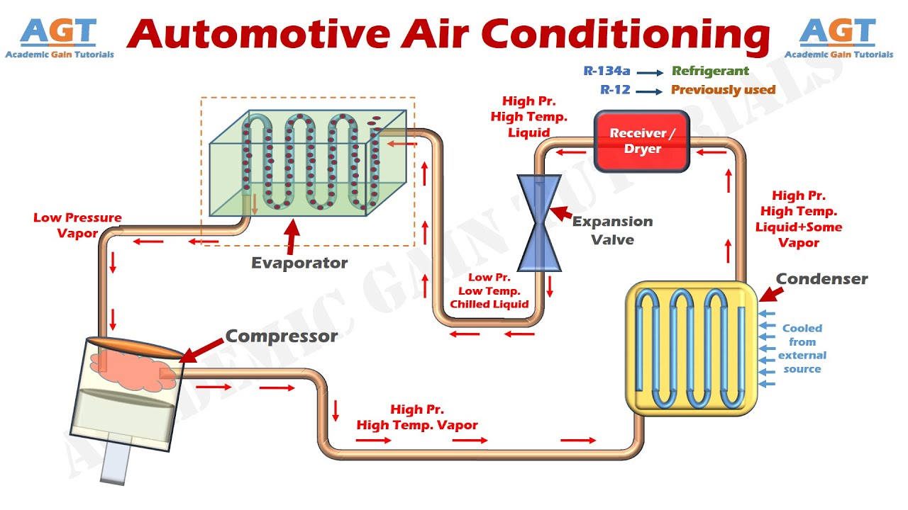
Diagram Of An Automotive Ac System
How Does AC Work in a Car? The air-conditioning system in a car works by manipulating refrigerant between a liquid and a gaseous state. As the refrigerant changes states, it absorbs heat and humidity from the vehicle and allows the system to give off cool, dry air.
TXV vs. OrificeTube Car AC Systems Operation and Diagnostics AxleAddict
Automotive A/C is made up of six major components; the compressor, evaporator (inside the car), condenser (in front of the radiator), hoses and fittings, a drier and a safety switch.
Simple Car A C Hose Diagram
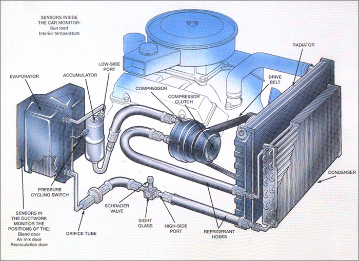
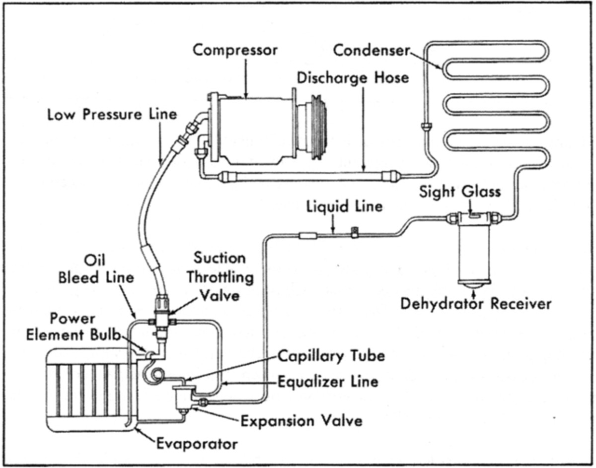
TYPICAL AUTOMOTIVE A/C SYSTEM DIAGRAM *Automotive A/C systems may vary from one application to another. Consult the owner's manual for system specific information. Low-Side Service Port
Schematic Diagram Of Automotive Ac System
Learn how a Orifice Tube A/C system works on a mobile vehicle. This is a beginning lesson on mobile A/C for anyone starting to work on Air Conditioning on ca.

What's the Difference Between Your Car’s Air Conditioner & Heater? In The Garage with
The car A/C works in two cycles: Refrigeration and Evaporative Cooling (evaporation and condensation). The primary purpose of the car air conditioner is to make the cabin ambiance comfortable for the occupants. Firstly, Air Conditioning is the process of making the air comfortable for the car's occupants.
CAR AIR CONDITIONING /AC/ SYSTEM FUNCTION COMPONENTS
Previous research has addressed the energy management of the A/C system for vehicles with traditional internal combustion engines (ICEs) [4] [5], where the A/C compressor is belt-driven by the ICE.

Auto Air Conditioning Diagram And Components
Displacement is controlled by a bellows actuated control valve located in the rear cylinder head. This control valve senses and responds to the system suction pressure or A/C system demand. Through regulation of compressor crankcase pressure, the wobble plate angle, and therefore compressor displacement is variable.

Car Air Conditioning System Wiring Diagram Pdf
If you look at the diagram above, you will see the arrows which show the direction that refrigerant flows through your AC system. There are slight variations between some systems, but this diagram is a good overall view of a generic AC system. This setup is typical for most imports and a few domestic cars.
