
Current Transformer Connection Diagram
The Basics of Current Transformers Current Transformers (CTs) can be used for monitoring current or for transforming primary current into reduced secondary current used for meters, relays, control equipment and other instruments.
Transformer Basics and Principles of Operation Basic Alternating Current (AC) Theory
Current transformer connections (primary/secondary) Errors Current or Ratio Error Phase Error Composite Error Accuracy Limit Current of Protection Current Transformers Class PX Current Transformers CT Winding Arrangements Wound primary type Bushing or bar primary type Core-Balance Current Transformers Summation Current Transformers
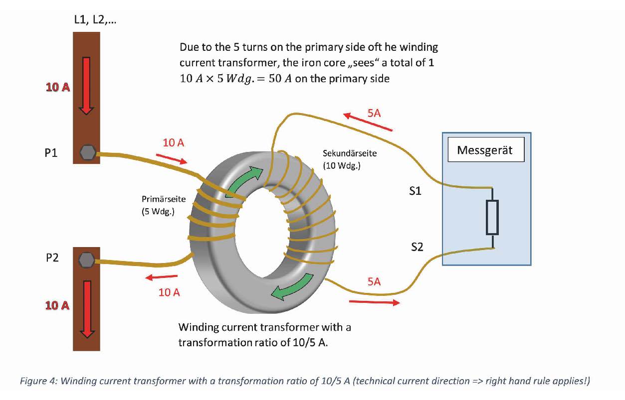
Winding Current Transformers in Low Voltage MBS AG EN
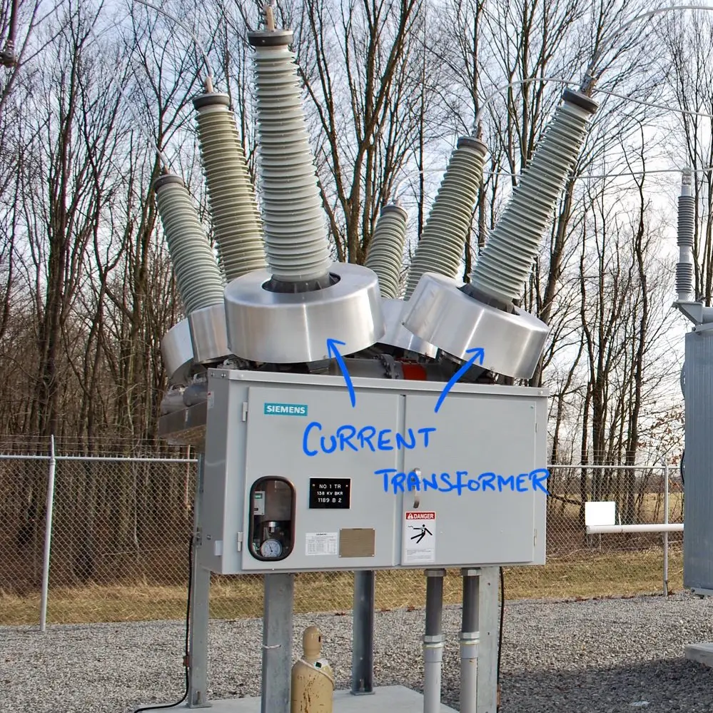
Current transformers reduce high voltage currents to a much lower value and provide a convenient way of safely monitoring the actual electrical current flowing in an AC transmission line using a standard ammeter. The principal of operation of a basic current transformer is slightly different from that of an ordinary voltage transformer.

Can I Use Multiple Current Transformers On The Same Phase? EKM Support Desk
In this one im connecting current transformers and meter modules for some 3 phase sub mains.This video follows up on the day i spent with john bagley, checko.
Current transformers (CT) working, types and connection
A current transformer is connected in series to the current-carrying conductor and an ammeter is connected to its secondary. The ammeter is arranged to give a full deflection with either 5A or 1A depending on the turns ratio of the CT. The ammeter's scale is adjusted according to the turns ratio. Working principle
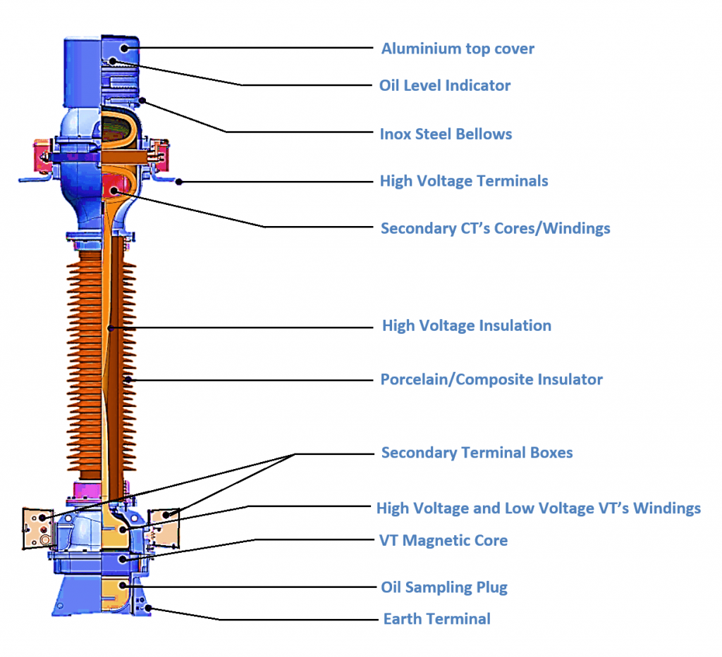
Combined Current and Voltage Transformer
A current transformer converts the current from high to low value (not the voltage). Common CT uses The two most common uses for a current transformer include: 1. Measuring and monitoring electric energy consumption The use of current transformers in metering is extensive as it allows for the safe measurement of high currents in lines.
Current Transformer Connection Diagram
What is a Transformer Connection? The primary and secondary winding of a three-phase transformer can be connected in different ways according to available terminals and the desired application. A three-phase transformer is constructed by three single-phase transformers on separate cores, or on one combined core.
Current Transformer Connection Diagram
In this connection the primary and secondary currents in all phases are not in phase. There is a 30-degree phase shift and hence, a compensation is needed. This compensation is performed through current transformer connections, or, internally, in a microprocessor differential relay. Figure 3 shows common transformer connections that are in use.
Easy understanding of 3phase transformer connections (DeltaDelta, WyeWye, DeltaWye and Wye
Wye and delta connections Zero-sequence current shunts Flux-summing CT 1. Auxiliary current transformers Auxiliary current transformers are used in many relaying applications for providing galvanic separation between the main CT secondary and some other circuit.
what is current transformer? different types of CT connections
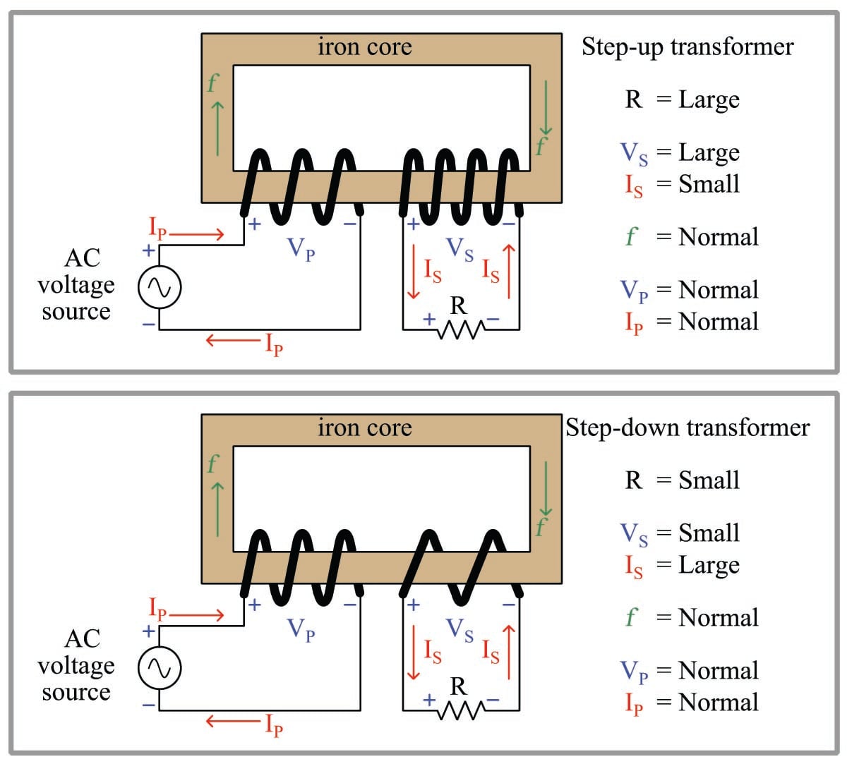
A current transformer is a transformer used to step down the line current to make it easier to measure. The total power in a transformer is the same on the primary and secondary sides. The only way to step down the current is by stepping up the voltage. Therefore, a current transformer is a modified step-up voltage transformer. Operation
Current Transformer Learn the Purpose, Cost, and Lead Time to Procure PEguru
This current transformer is an essential part of the power system. The basics of the current transformer including construction, applications, working principles are going to be discussed in this article. Moreover, some practical aspects such as grounding and connections of current transformer and associated errors will be examined comprehensively.
Three Phase Transformer Connections ElectricalWorkbook
Subscribed 413K views 3 years ago Current transformers are used extensively in metering and circuit protection. Eaton's Power Systems Experience Center is the ideal place to learn how to properly.
The Essentials Of Current Transformers In Power Circuits (Theory and Practice) EEP
The proper application of current and voltage transformers involves the consideration of several requirements, as follows: mechanical construction, type of insulation (dry or liquid), ratio in terms of primary and secondary currents or voltages, continuous thermal rating, short-time thermal and mechanical ratings, insulation class, impulse level.

Can I Pass Multiple Wires Through a Current Transformer? EKM Support Desk
A clamp-on ammeter is a type of split-core current transformer; the jaws are opened and placed around the conductor to measure the amperage flowing in the conductor. 3. Bar-type current transformers already have the secondary winding around a bar. The supply conductor is bolted to each end of the bar, and current then flows through the bar.
Current Transformer Wiring Diagrams
Figure 1: Leakage Flux Associated with T-Class Current Transformers . Thermal Ratings Current transformer continuous ratings can be increased beyond nominal by use of a continuous thermal current rating factor. This factor is defined in ANSI/IEEE C57.13-1993(R2003) as:
Connections and working principles of threephase distribution transformers EEP
In most cases, the primary of a current transformer is a single wire or busbar ,and the secondary is wound on a laminated magnetic core, placed around the conductor in which the current needs to be measured, as illustrated in figure 1.
