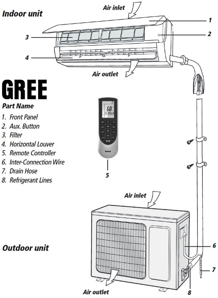
Gree Split Air Conditioner Wiring Diagram
How to read AC or air conditioner condenser unit wiring diagram / schematic. I go over 4 AC condenser wiring diagrams and explain how to read them and what a.

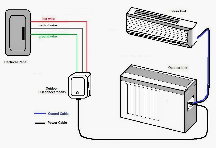
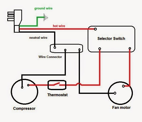
How to Wire an Air Conditioner for Control 5 Wires
HVAC system diagrams and schematics fall into three different categories: ladder, line, and installation diagrams. Here's how those break down. Ladder Diagrams.

Electrical Wiring Air Conditioner
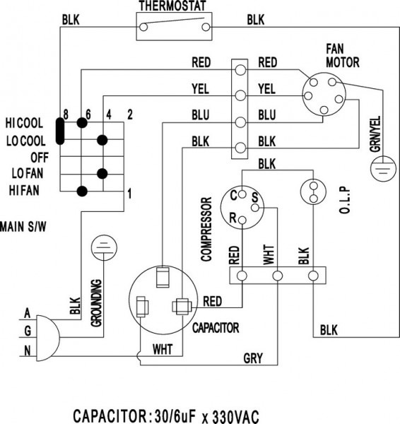
Wiring diagrams are used for the installation of the HVAC equipment, trouble shooting, or locating an electrical device in the control panel or within the unit. There are differences between the type of diagrams based on what they're used for. Schematic Wiring Diagram often called a Ladder Diagram and a Pictorial Diagram
Air Conditioner Wiring Diagram Pdf Window Ac Csr Carrier Split Car
24V or low-voltage heating and cooling systems include one or more of these components: Heating: Gas furnace, either natural gas (NG) or propane (LP), oil furnace, heat pump with or without auxiliary heat strips Cooling: Air conditioner, PTAC (packaged terminal air conditioner), heat pump Accessories: Humidifier, dehumidifier, ERV/HRV ventilator, air purifier and other air quality equipment

Schematic Wiring Diagram Of Aircon
WIRING DIAGRAM MANUAL Split System Horizontal Air Conditioner 421 03 1600 00 3 Specifications subject to change without notice. 345082−101 — (C,H,T)SA660GKB 345082-101 REV. A 1. Compressor and fan motor furnished with inherent thermal protection. 2. To be wired in accordance with National Electric Code (N.E.C.) and local codes. 3.
Central Air Conditioner Wiring Diagram Download Wiring Diagram Sample
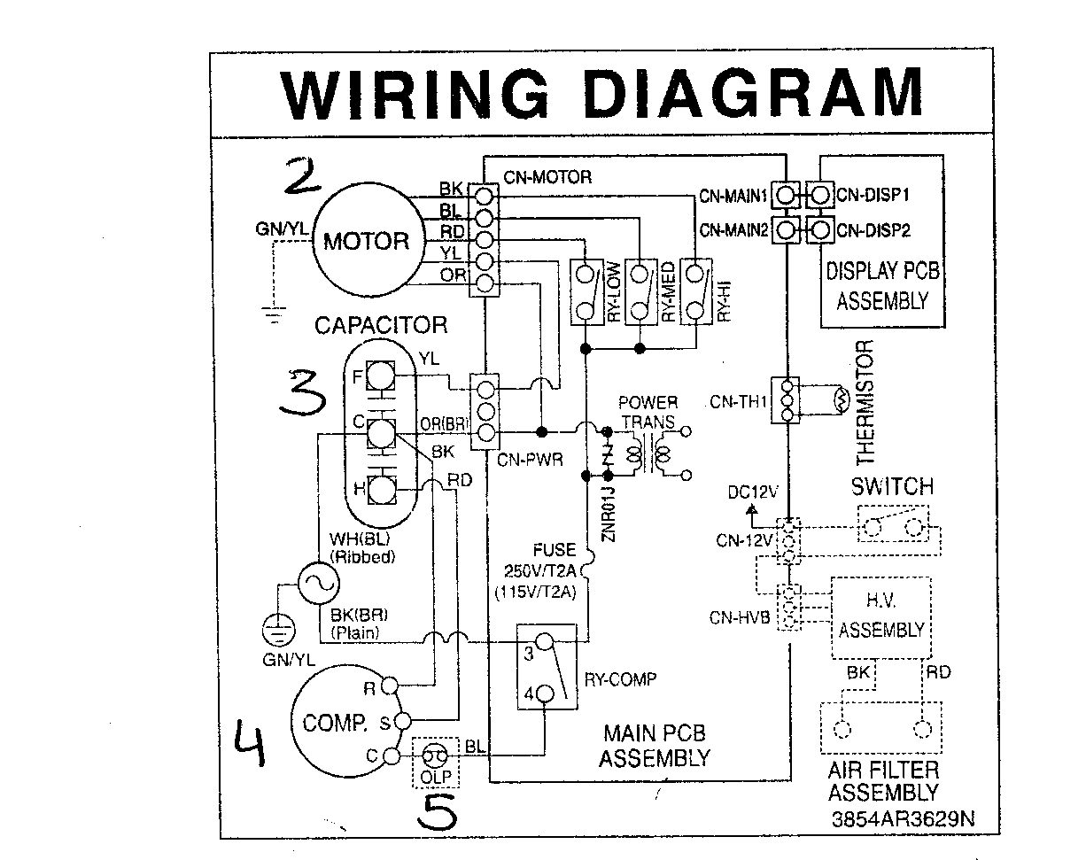
The diagrams also show the location of all the components, including the compressor, evaporator, fan motor, condenser, and thermostat. A Goodman air conditioner wiring diagram can be located in the owner's manual, in the back of the unit, or on the manufacturer's website. If the diagram is not available, a qualified technician can help locate it.
Hvac Split System Wiring Diagram
The Line Diagram, The installation diagram. 3.1 The Ladder Diagram It is the most common type of wiring Diagrams. It is called ladder because the symbols that are used to represent the components in the system have been placed on the rungs of a ladder. ladder diagrams will be referred to as "schematic" diagrams, or simply "schematics."

Air Conditioner Wiring Diagram Pdf
🔌 Learn how to correctly wire a single-phase split air conditioning system with this comprehensive wiring diagram tutorial. Whether you're a DIY enthusiast.

Air Conditioner Schematic Wiring Diagram
A detailed diagram illustrating where the wires go for 5 wire air conditioner and heating system control Lastly, resource and related links to help you with wiring and installing a thermostat How to Wire an Air Conditioner for Control 5 Wires
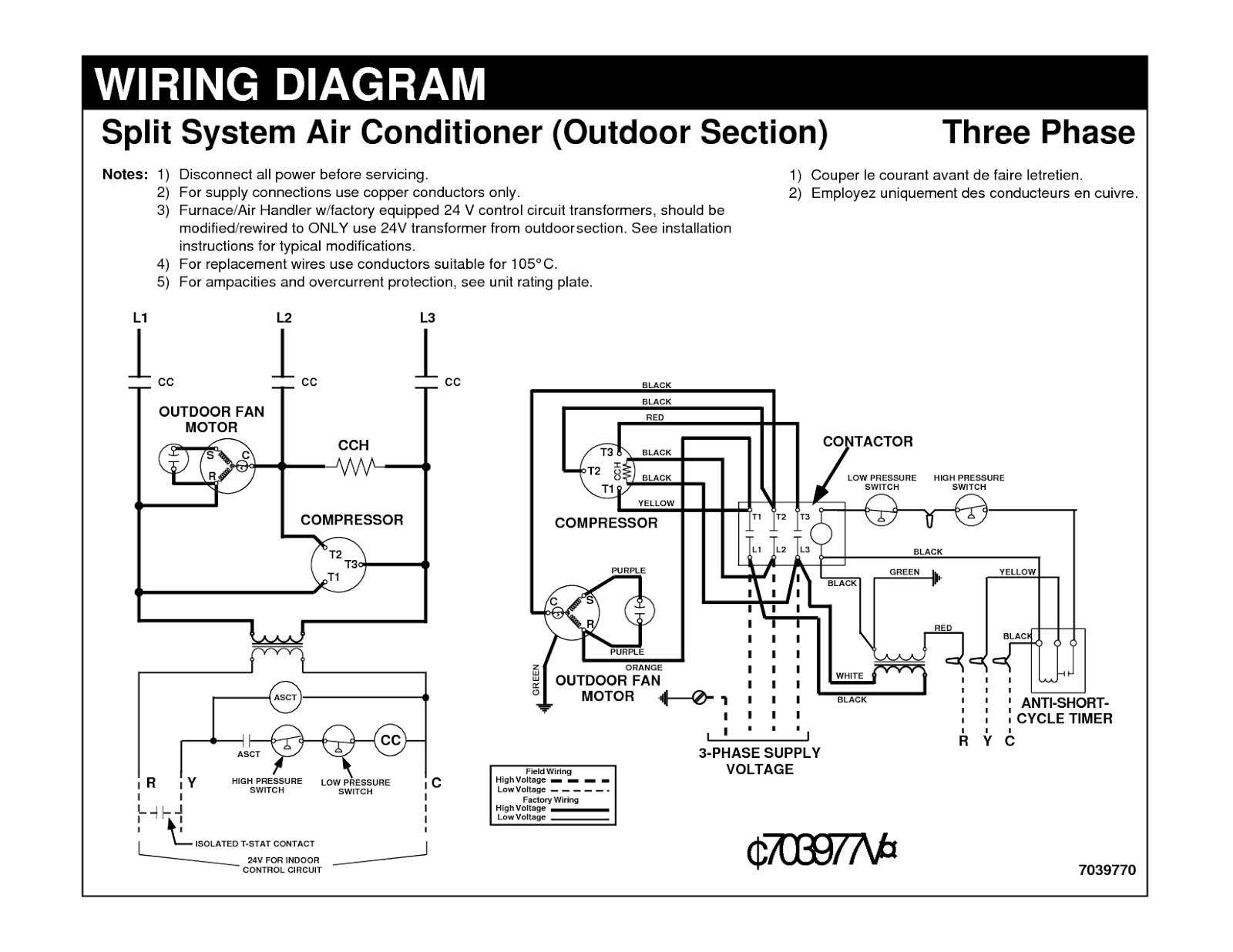
Electrical Wiring Diagrams for Air Conditioning Systems Part Two
0:00 / 5:42 • Intro How to Read Wiring Diagrams for HVAC Equipment MEP Academy 21.5K subscribers Subscribe Subscribed 16K views 11 months ago Electrical and Power Learn how to read HVAC.
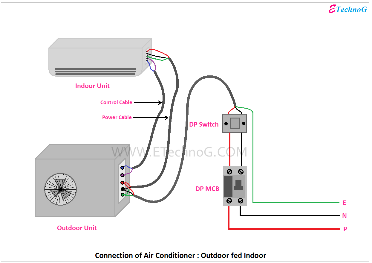
Air Conditioner Connection and Wiring Diagram ETechnoG
Types of Electrical Wiring Diagrams For Air Conditioning Systems, How to read Electrical Wiring Diagrams? Today, I will explain Electrical Wiring for different Air-Conditioning Systems Types and Equipment. Third: Electrical Wiring Diagrams for Air-Conditioning Systems - Continued

Wiring Diagram Of Package Ac
We walk through some of the basics and most common symbols associated with reading air conditioner wiring diagrams. Whenever you approach a wiring diagram, look at the whole thing, especially the legend and notes. In many cases, factory wiring will show up as solid lines and field wiring will show up as dashed lines.

Wiring Diagram Of Air Conditioner Wiring Diagram Schemas
6 awg. 50 amps. 25 mm2. 4 awg. 60 amps. Wire Size for Single Phase 230V. Apart from using the air conditioner capacity to size wires, you also can use the amperage to size wires. In fact, it is better this way. From the above single-phase table, the minimum wire size needed for 20 amps is 4mm2 or 12-gauge wire.

Home Air Conditioner Electrical Diagram
Check the plate with a level, and mark the screw holes with your pencil. If applicable, drill guide holes before adding anchors to the wall. Pull the wires through the opening of the thermostat's backplate. Attach the back plate to the wall with the provided screws. Check to make sure the thermostat is secure.
Electrical Wiring Diagrams for Air Conditioning Systems Part One
A mini-split heat pump system is basically an air conditioning unit that runs in reverse, providing both cooling and heating. You wire one just like a dedicated air conditioner. We asked master electrician John Williamson to explain the process.
Wiring Air Conditioner Electrical Wiring Diagrams Okyotech The air
A wiring diagram for split AC units is a diagram that explains the connections between the components of a split air conditioning system. The diagram may include the main power supply, the indoor unit, compressor, condenser, blower motor, thermostat, and other components. It also may show how the electrical wires are connected from the main.
