ON Delay Timer Circuit Diagram With Relay Using Capacitor
It can be done as explained below: Connect any arbitrarily selected resistor above 100K in place of P1/R2 in the upper circuit. Switch ON and carefully note down after how much time pin#3 of upper IC 4060 becomes HIGH. This will be your " sample delay ".
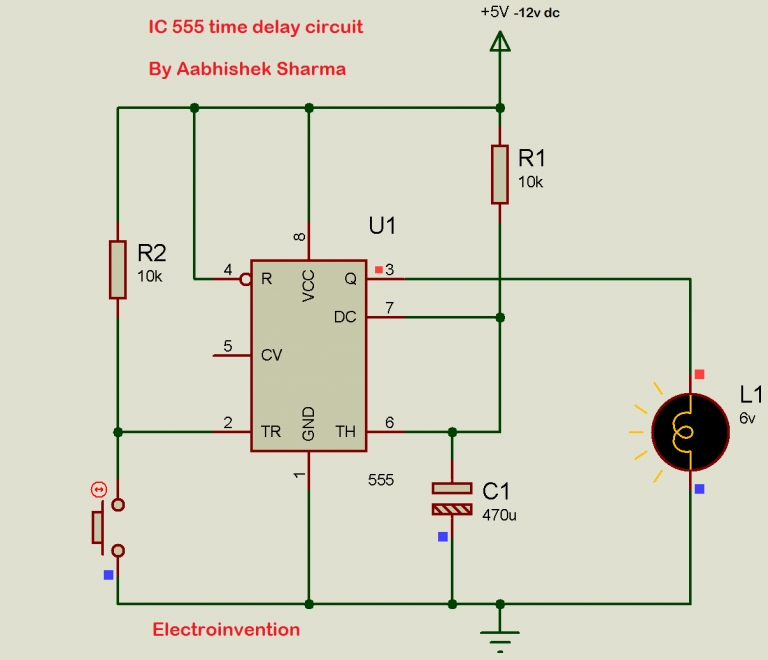
IC 555 Delay Timer circuit Easy timer circuit on off delay circuit
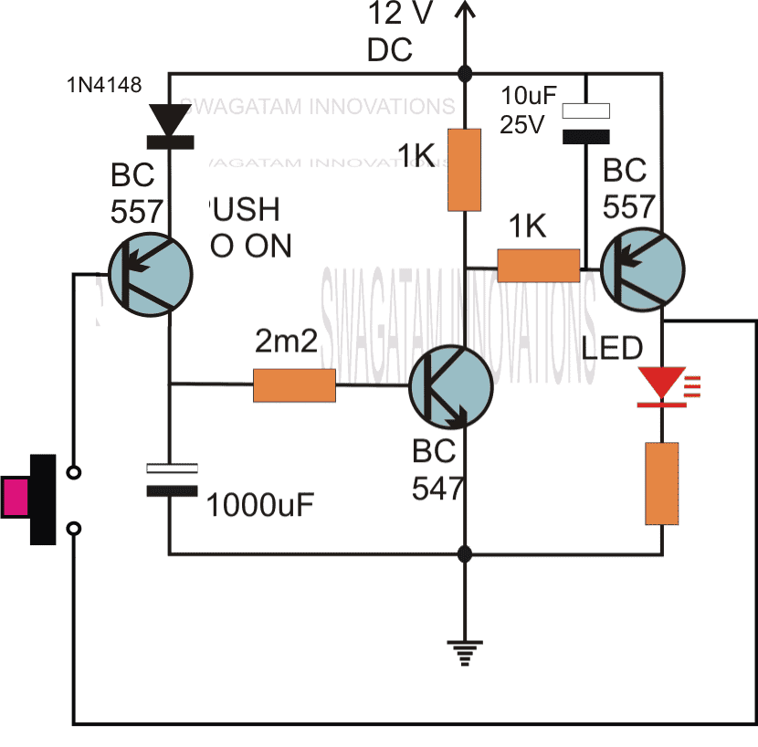
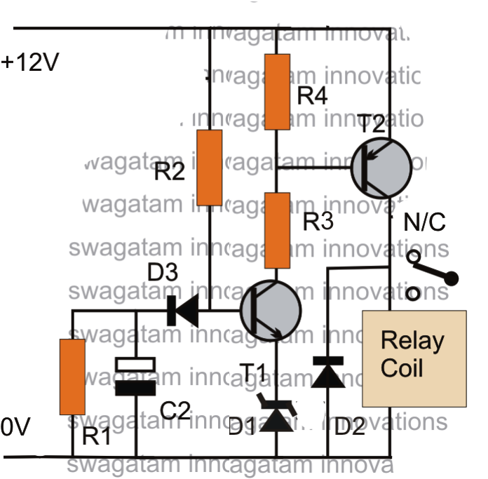
A push button is used to initiate the circuit. On depressing the button momentarily, a positive voltage from the supply line enters the base resistor and switches ON the transistor and subsequently the LED. However in the course of the above action, the capacitor also gets charged fully.

how to make time delay circuit YouTube
How is a time delay switching circuit developed? Time delay switching circuit can be developed using, - Passive electronics topology - Integrated circuit topology - Micro-controller topology Passive electronics uses electronics like resistor,capacitor,diode and many more. This topology, is what we are going to focus in this video demonstration.
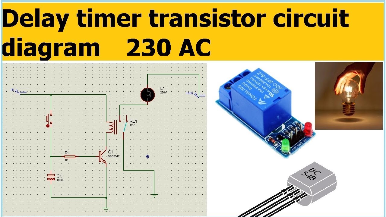
Delay timer transistor circuit diagram 230 AC delay off timer circuit YouTube
Step 1: Gather the Materials To build the basic circuit you will need: A MOSFET. I used an IRF3205 A capacitor Two resistors Jumper wires Ask Question Step 2: Assemble the Circuit Assemble the circuit according to the schematic. Ask Question Step 3: Testing and Tuning Its now time to test the circuit and add the extras.
Time Delay Circuit Diagram
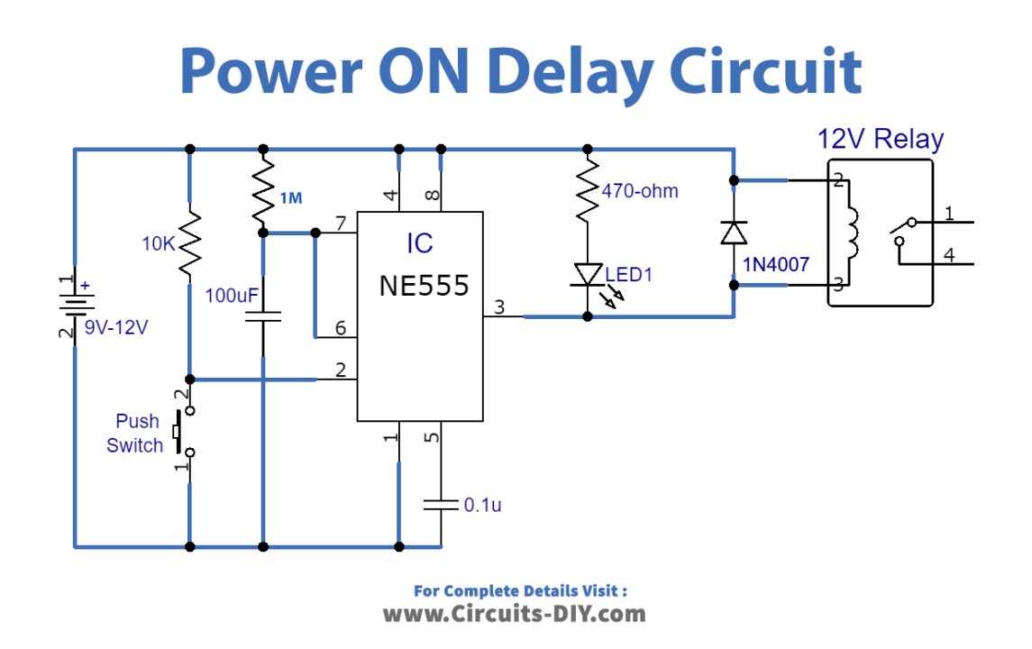
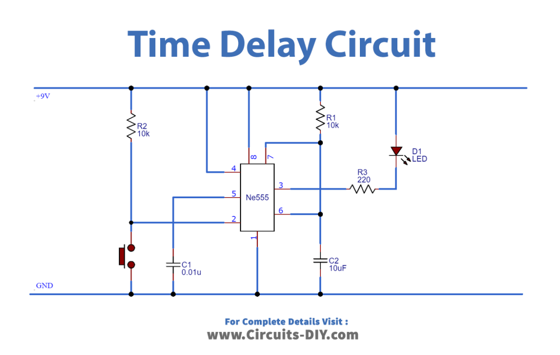
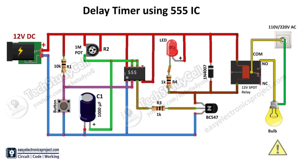
When the pushbutton is pressed, the countdown timer starts and the green LED turns on after the particular time (defined by the formula T= 1.1*R1*C1) the 555 timer goes into a stable state, where the Red LED turns ON and the green LED turns Off. You can increase and decrease the time delay by using the 100K potentiometer.
Time Delay Circuit Using 555 Timer
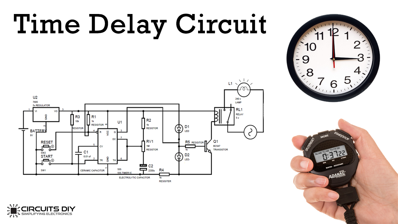
330Ω — 1 1000µF / 25V — 1 100µF / 25V — 1 1N4007 — 1 LEDs — 2 Circuit Design of Time Delay Relay A 1KΩ resistor, a 100KΩ variable resistor and another 1KΩ resistor are connected in series between the supply and ground. The wiper of the variable resistor is connected to the positive terminal of a 1000µF capacitor.

Time Delay Relay using 555 Timer, Proteus Simulation and PCB Design
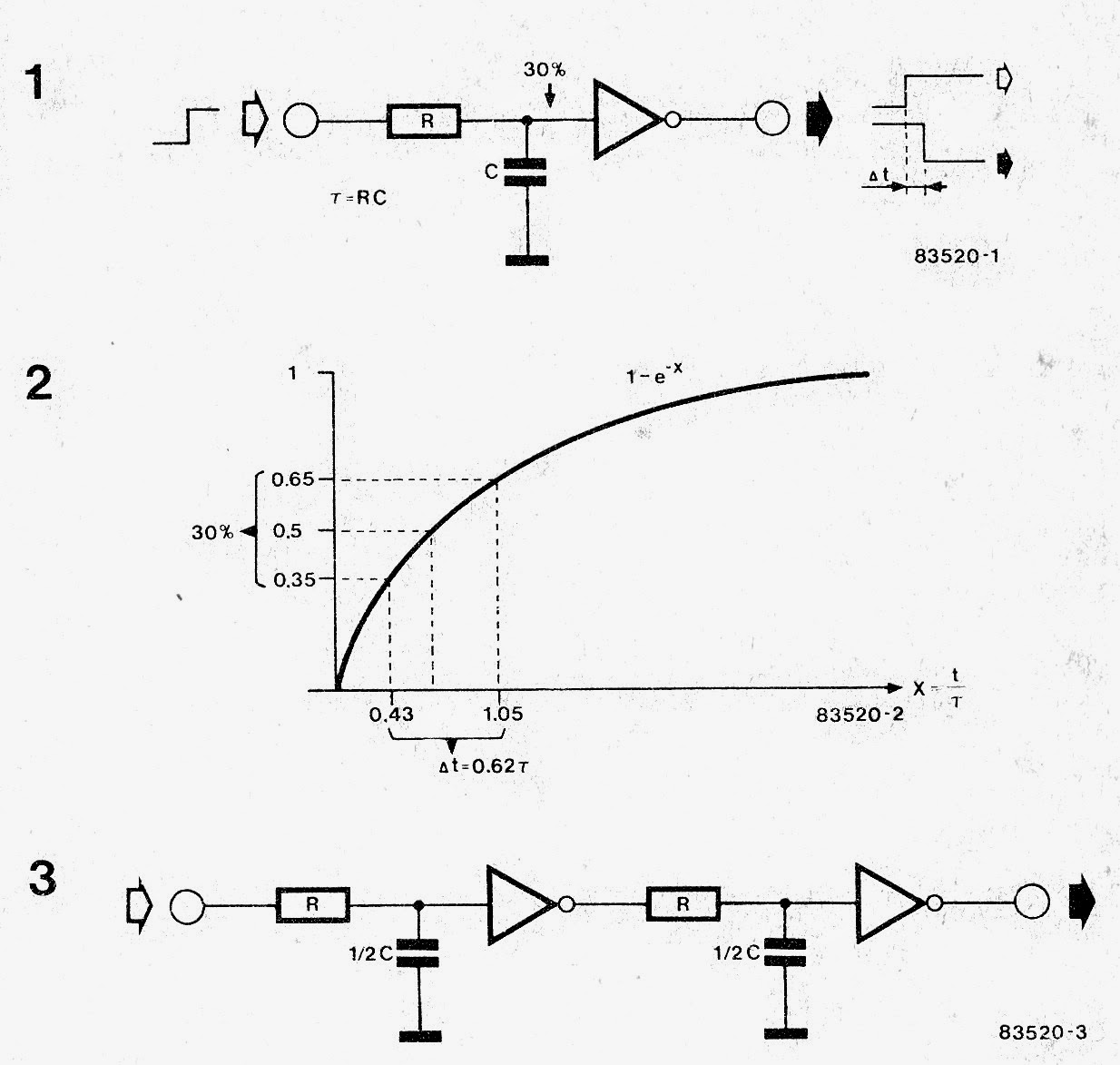
You can calculate the delay time of your RC delay element with a simple formula: That's the RC time constant, also called tau, which is written like τ. It gives you the time it takes for the voltage to rise from zero to approximately 63.2% of the voltage you apply.
Time Delay Circuit Using 555 Timer
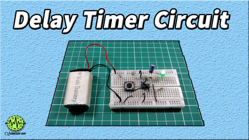
in this video, I show how to build a simple delay timer circuit. With such timer you'll be able to turn a light bulb or any other appliances on or off, for a.

How To Make On/Off Delay Timer Circuit using 555 Timer IC DIY Project
#BC547#DelayCircuit#IETIn this video you will learn how to make a simple Delay circuit using BC547 Transistor . This is the easiest way to make Delay Circu.
Simple Time Delay Circuit using 555 Timer
Time Delay Relay can provide a short delay after power is turned on and before switching on the device. The working is very simple and is explained below. The circuit is based on the RC time delay and Zener controlled switch. When the power to the circuit is turned on, the 1000µF capacitor charges through the 100KΩ variable resistor.
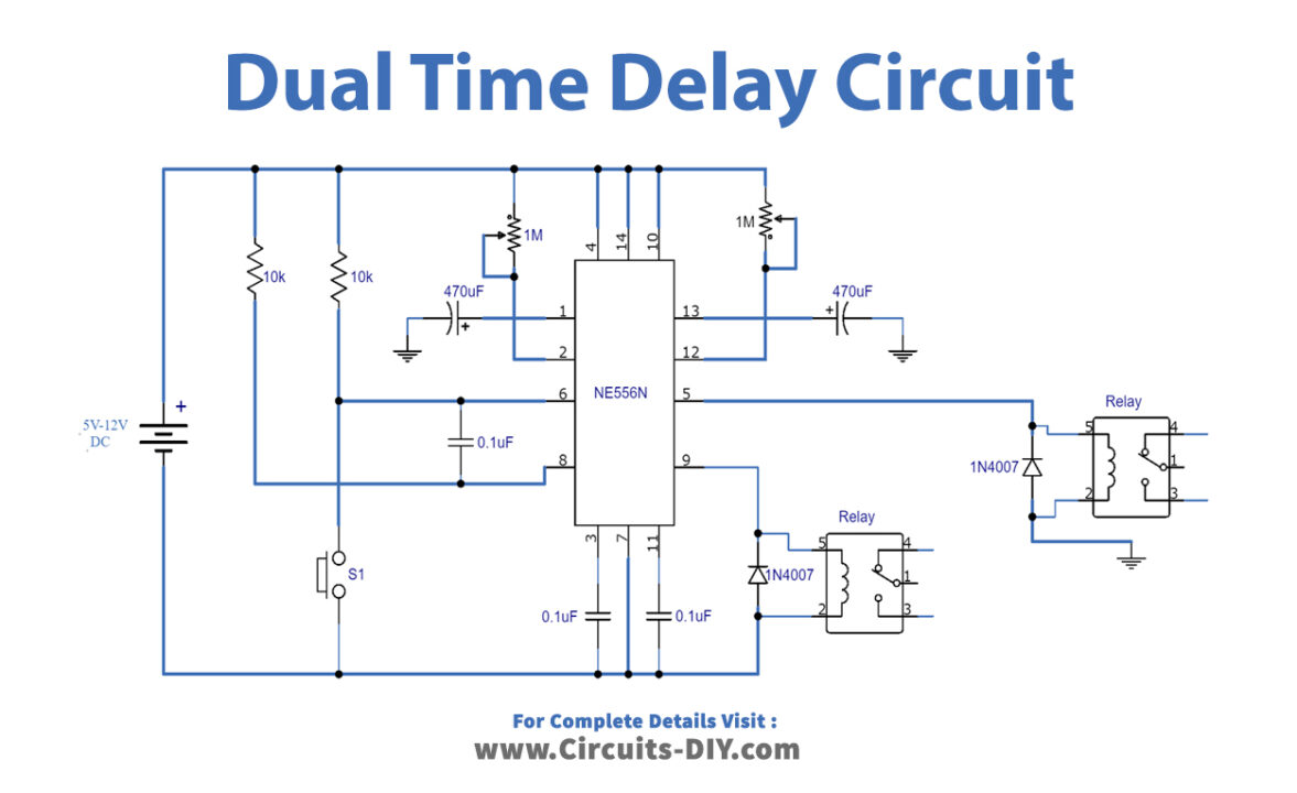
Dual Time Delay Relays Using 556 IC
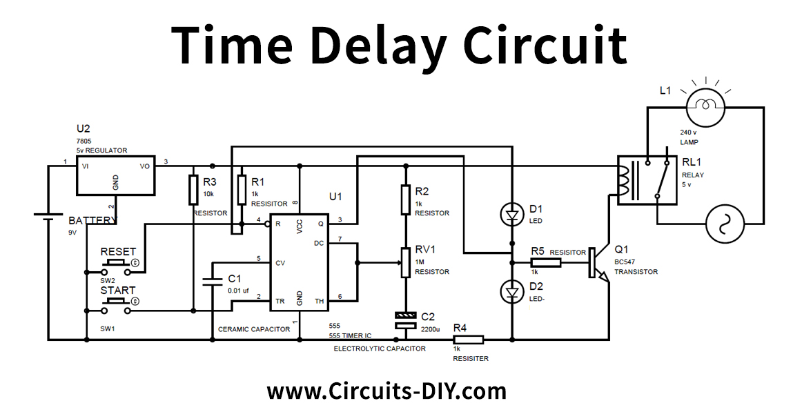
Before going into detail of Time Delay Circuit, first we need to learn about 555 Timer IC first. Below you can find the pin diagram of 555 timer IC along with the details of each pin. Pin 1. Ground: This pin should be connected to ground. Pin 2. TRIGGER: Trigger pin is dragged from the negative input of comparator two.
Simple Delay Timer Circuits Explained Homemade Circuit Projects
In this video, I will explain the working of the transistor timer circuit, also known as delay timer or turn on circuit, which is an example of a hobby elect.
Time Delay Relay circuit using 555 timer IC Share Project PCBWay
Make a Simple Capacitor/Transistor Timing Circuit 21 Aug 2018 Published By Unintended circuit delays can be a real nuisance. However, controlled delays may prove quite useful in some situations, as they allow actions to start at a predefined time.
Make this Simple Delay ON Timer Circuit Application Note Included Circuit Diagram Centre
Time-delay relays can be constructed to delay armature motion on coil energization, de-energization, or both.Time-delay relay contacts must be specified not only as either normally-open or normally-closed but whether the delay operates in the direction of closing or in the direction of opening.
Simple Delay Timer Circuit How to Make and Calculate Schematics World
In this 555 timer project, I have shown how to make a time delay relay circuit using 555 timer IC to automatically turn Off the switch after a predefined delay. You can also adjust the off delay time up to 20 minutes with a 1M POT.
Time Delay Circuit with Relay
4 Application. In this tutorial, we will show you how to make a Time Delay Circuit using 555 Timer IC. The main principle of this circuit is to generate a pulse signal after some time delay. A time delay circuit can be useful for any circuit that needs a delay before the output turns on. In order to obtain time delay, we are using a 555 timer.
