FM Stereo Transmitter Communication_Circuit Circuit Diagram
The FM transmitter is a single transistor circuit. In the telecommunication, the frequency modulation (FM) transfers the information by varying the frequency of the carrier wave according to the message signal. Generally, the FM transmitter uses VHF radio frequencies of 87.5 to 108.0 MHz to transmit & receive the FM signal.
Audio kit HIFI Stereo Multiplexer for FM transmitter with NJM2035 I.C. circuit
5/5 based on 1 review. Radio Marca 103.5 broadcast radio station in Madrid, Community of Madrid, Spain providing Sports Talk & News programs. Radio Marca, Escucha la radio que hace afición, FM 103.5, Madrid. Live stream plus station schedule and song playlist. Listen to your favorite radio stations at Streema.
Electronic Kits, Electronic Projects, Electronic Schematics, DIY Electronics
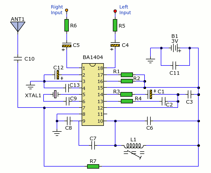
The implementation is of this circuit easy. With the BA1404 HI-FI Stereo transmitter, you will be able to transmit MP3 music from your mp3 player, computer, TV / SAT receiver, and many other audio sources. In this ckt mic not use but directly audio input connects with the audio jack. The Ba1404 ic is a good quality digital Fm transmitter.

BA1404 3V Stereo FM Transmitter Electronics Infoline Electronics Infoline
A FM transmitter is a device that uses the principles of frequency modulation to broadcast sound supplied at its input. Typical FM transmitter design's usually follow the block diagram below; The signal strength of audio inputs into the transmitter is usually low therefore an amplifier is usually built to bring the signal level up.
Stereo FM Transmitter with BA1404
An exceptional stereo audio FM wireless transmitter circuit is presented below. The circuit relies upon the IC BA1404 from ROHM Semiconductors. BA1404 is a monolithic FM stereo modulator which includes integrated stereo modulator, FM modulator, RF amplifier circuitry.
stereo FM transmitter Schematic Power Amplifier and Layout
About The Circuit: These is the exact description of Art Swan, the circuit's Author, "This miniature transmitter is easy to construct and can be picked up on any standard FM receiver. It has a range of up to 1/4 mile or more.
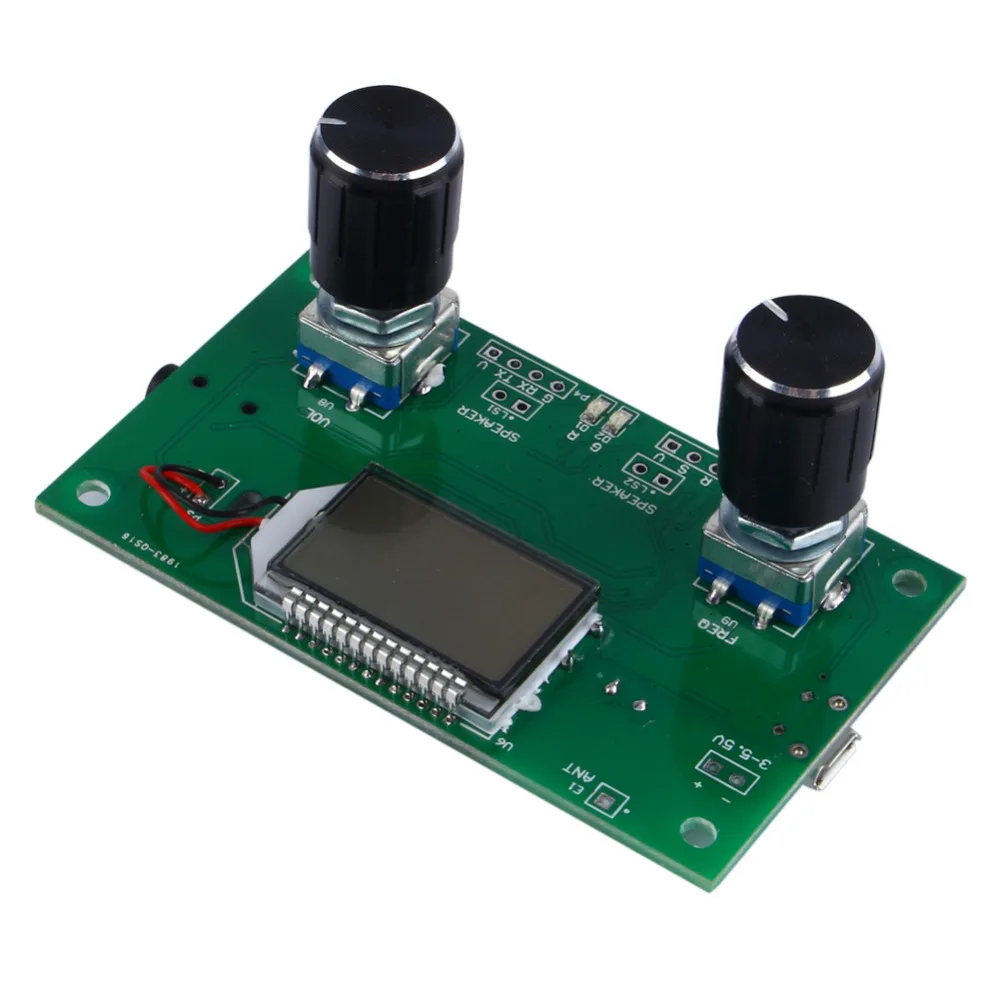
Buy Digital Stereo FM Radio Receiver Module and FM Modulation Phase Locked Loop
It is a small power fm transmitter that allows data transmission RDS (Radio Data System). Incorporated DSP generates stable stereo signal and attachment RDS data. NS741 applications Wireless microphone Cd and portable mp3 Cell phones NS741 characteristics covered band 76 to 108 MHz stereo modulation RDS transmission Automatic level control
FM Stereo Transmitter using BA1404 IC
BA1404 is a IC designed for fm mini stereo transmitters. It can be used as a pc fm transmitter, ipod fm transmitter, mp3 transmitter or even car fm transmitter because it has a small pcb dimension ( can fit anyplace ) and maximum 3V power supply. It has a good frequency stability due the high quality 3.5 turns coil and a crystal clear stereo.
38KHZ_stereo transmitter_fm_ba1404 Suggested PCB mounting stereo FM transmitter with
To transmit stereo music, FM is enhanced by stereo multiplexing which carries both L and R audio channel content. With the digital age, Radio Data System (RDS) enables FM to carry text information such as traffic, weather, and radio station information which can be displayed on the end-user's device interface.
Радиопередатчик FM на базе УМЗЧ или готового усилителя НЧ Форум радиолюбителей
Stereo FM Transmitter using BA1404 IC - This is a stereo FM transmitter circuit using an IC from Rohmm semiconductors named BA1404 - which is a monolithic IC and has a built-in stereo modulator, FM modulator, RF amplifier circuitries. This FM modulator can be operated between 76 to 108Mhz.

FM Transmitter circuit only with 5 components YouTube
A simple and high quality FM transmitter circuit designed based on the BA1404 IC .This FM transmitter circuit can be operated from a 3 V battery.
car stereo 6 channel diagram
The circuit is powered by a 9V power supply. Transistor Q1 is a high gain audio amplifier that amplifies the sound detected by the electret microphone. The output of Q1 is fed into the frequency modulating circuit created by transistor Q2, inductor L1, and variable capacitor C5.
fm transmitter circuit Page 10 RF Circuits Next.gr
The transmitter can then be connected to a source of audio, such as a phone or computer, to broadcast music or other audio content. In this project, I have introduced a compact stereo digital FM transmitter circuit that operates in the frequency range of 87MHz to 108MHz. The frequency can be adjusted using two tactile push-buttons, with a 0.
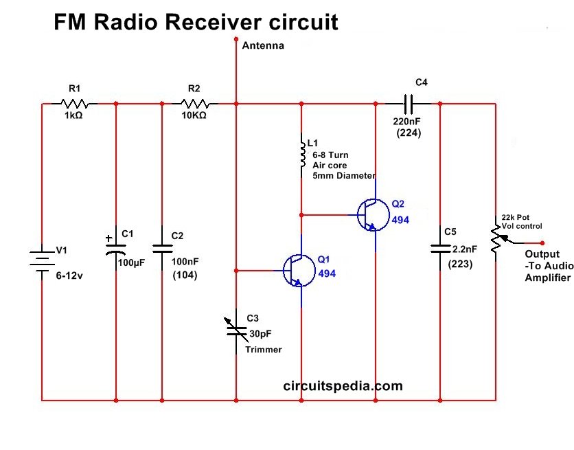
Very simple FM Radio Receiver Circuit circuitspedia
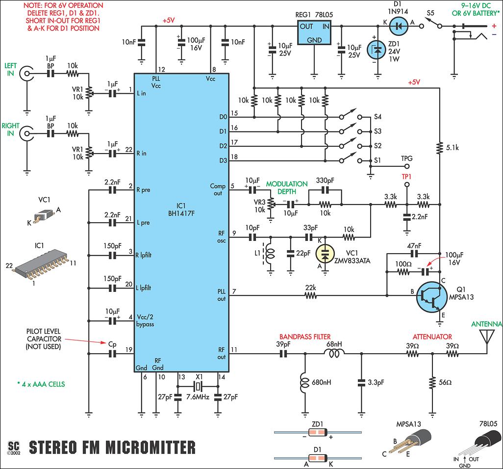
The circuit shown here is of a good Stereo FM transmitter that can transmit high-quality signals up to a range of 70 feet. The circuit is based on BH1417 PLL stereo transmitter IC from Rhom semiconductors.
BH1417 PLL Stereo FM Transmitter simple schematic diagram
FM — frequency modulation. modulator — a circuit designed to add information to a carrier. modulation index pertains to an FM or PM transmitter. The ratio between carrier-frequency deviation (in hertz) and modulating frequency (also in hertz).
Long Range Rf Transmitter Circuit Diagram
Circuit Components: FM Transmitter Circuit Design: Design of Audio Pre-amplifier: Here we are designing a simple single stage common emitter amplifier as the pre-amplifier. a) Selection of Vcc: Here we have selected the NPN Bipolar Junction Transistor, BC109. Since VCEO for this transistor is around 40V, we choose a much lesser Vcc, of about 9V.
