
UC3843 Feedback Question and How to Debug Power management forum Power management TI E2E
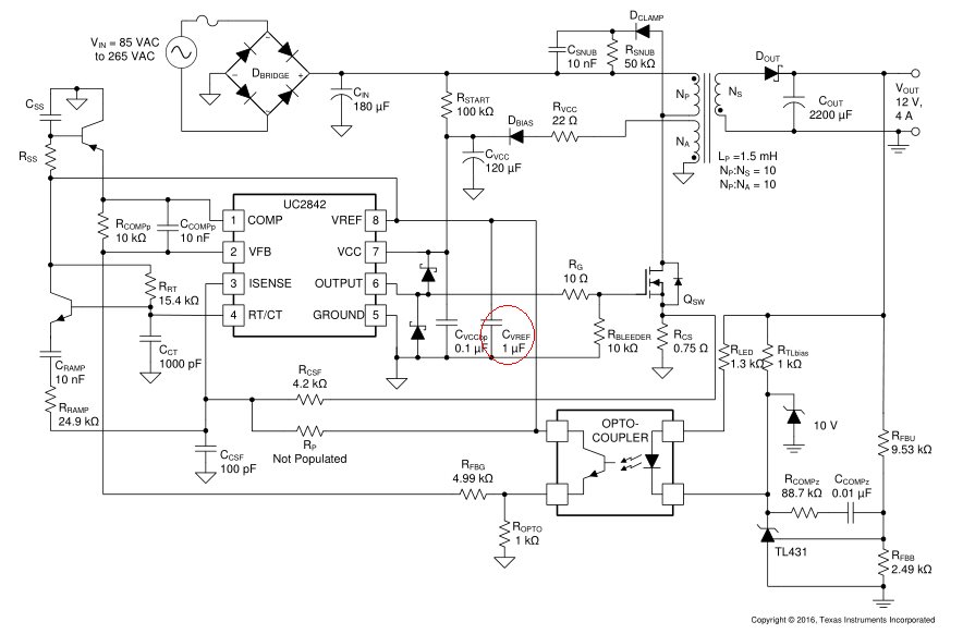
Before applying input voltage, isolate the UC3843's VCC input and power it with a benchtop DC supply. Gradually raise the DC input on VCC and observe the UVLO threshold turn-on. You can check the signals at VCC, OUT, VREF, and RT/CT, verify proper VCC and expected VREF as well as PWM output at your desired frequency (set with RT/CT values).
NTE Electronics Circuit Power Supply Switching IC UC3843
Debashis Das Author 12V/27W SMPS Circuit with UC3843 Switching Mode Power Supply or simply SMPS is a type of Power Supply Unit (PSU) that uses a switching device (such as transistor or MOSFET) to convert the source that can be AC or DC to a constant DC voltage.

Laptop Power Bank INVERTER with UC3843 YouTube
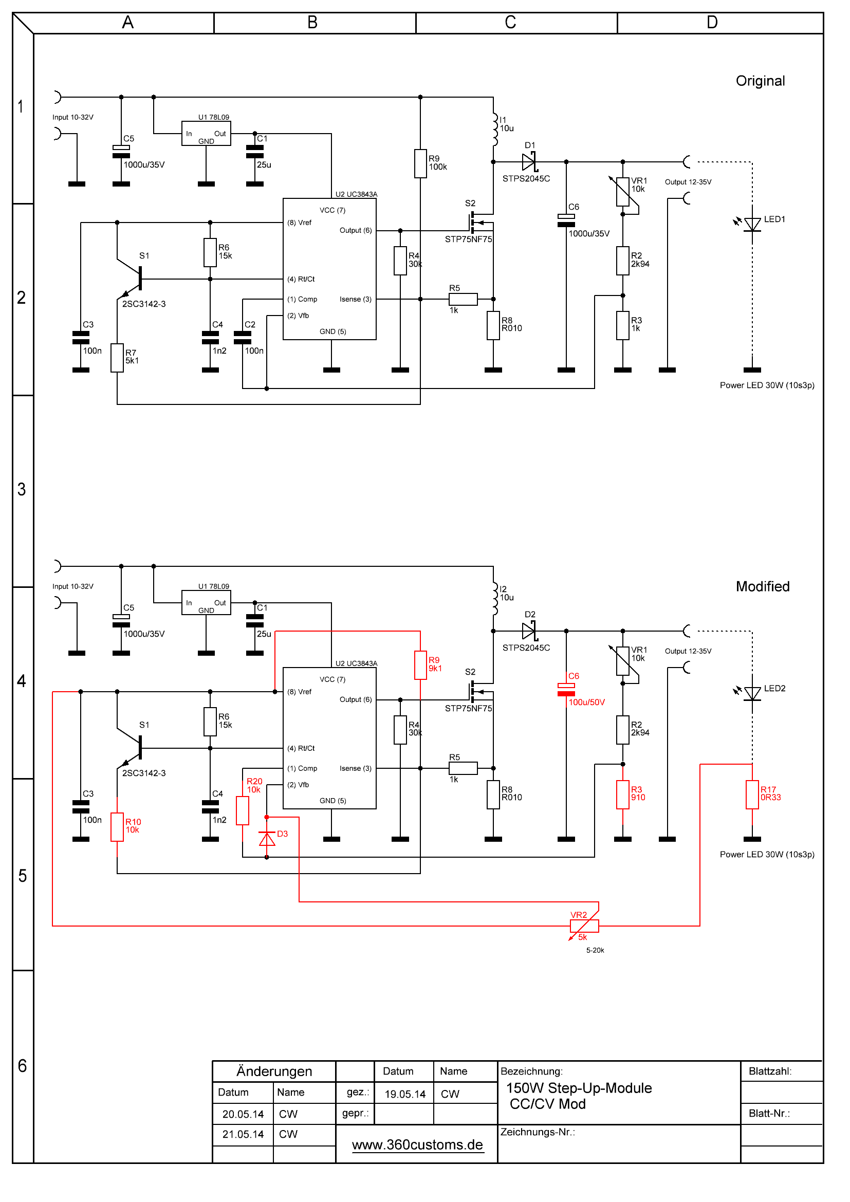
100W Watts Boost Converter with CV and CC This circuit is modification of 150W Boost Converter Schematic to have current limit. Explained at 10/30/50/100W LED application driver (UC3843A). 8-16V to 12V Source: https://dren.dk/carpower.html AC to DC 19V Single Output Power Supply

UC3843組成的車載電源適配器電路圖 研發互助社區
UC3843 Specifications Current-Mode PWM controller Operating Voltage: 7.0V to 8.2V Output pin current: 1A Analog input range: -0.3 to 6.3V Oscillation Frequency: 52 Typically Gain: 3V Maximum source current: 22mA Low Output Voltage: 0.08V High Output Voltage: 13.5V UC3843 Equivalent/Substitute UC3842 Alternatives PWM controller ICs
uc3843 smps circuit diagram Wiring Diagram and Schematics
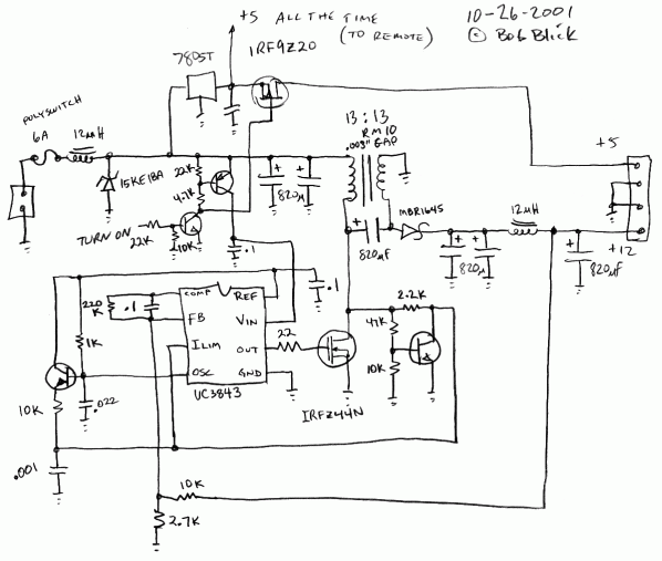
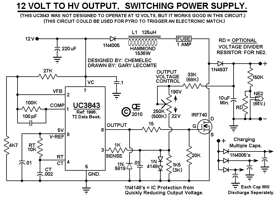
This Circuit is based on a UC3843 Integrated Circuit. It does Not allow for Feedback control of the output voltage. The output voltage is totally determined by the "Turns Ratio" in Transformer "T1". The Useable, Continuous Power Output is approximatey 25 watts or so. It could be used as a small Power Supply or a Battery Charger.
UC3843 Electronics Notes
The UCx84x series of control integrated circuits provide the features that are necessary to implement off-line or DC-to-DC fixed-frequency current-mode control schemes, with a minimum number of external components.
Pegs walk Bridge pier uc3843 power supply schematic
The UC3843 IC is a versatile PWM controller integrated circuit that is widely used in DC to DC converters. It is designed for power supply applications and offers various features like internal temperature compensation, soft-start capability, and overvoltage protection. The IC operates at a fixed frequency of 50 kHz, which ensures stable and.

SCHEMATIC WITH POWER SUPPLY ElectronicsLab Electronics lab, Power supply, Circuit board design
Use of the comp pin on the UC3843 for the feedback point is pretty normal too. Regarding the schematic, it's badly segregated into almost pointless sub-sections that make it hard to decipher. Having said that, the simplicity of the basic circuit means it took me 5 minutes instead of 2 minutes.
14+ Uc3842 Power Supply Schematic Robhosking Diagram
Figure 1 shows the schematic diagram of the DC to DC boost converter. As it is clear, the heart of the circuit is the UC3843 chip [1]. Figure 1. Schematic diagram of the UC3843 DC to DC boost converter. C1 and C2 have been used to reduce the input noises. L1, D1, and Q1 build a boost conversion network. L1 is an 8A to 10A 100uH inductor.

Uc3843 Circuit Diagram Headcontrolsystem
A. Circuit Analysis. Figure 1 shows the schematic diagram of the DC to DC boost converter. As it is clear, the heart of the circuit is the UC3843 chip [1]. Figure 1, Schematic diagram of the UC3843 DC to DC boost converter. C1 and C2 have been used to reduce the input noises. L1, D1, and Q1 build a boost conversion network.

TL494 Adjustable Switching Power Supply For DIY Projects YouTube
PowerStream Quality

Pegs walk Bridge pier uc3843 power supply schematic
Description The UC3842/UC3843/UC3844/UC3845 are fixed frequencycurrent-mode PWM controller. They are specially designed for Off-Line and DC to DC converter applications with minimum external components.

switch mode power supply Can someone help me understand this SMPS circuit with the UC3843
The UVLO circuit VCC isinsures adequa that e the UC3842/3/4/5 fully operational before enabling the output stage. Figure 5 shows that the UVLO turn-on and turn-off thresholds are fixed internally at 16V and 10V re-spectively. The 6V Vcc hysteresis o cillations prevents during power sequencing. Figure 6 shows supply current requirements.

UC3843 Tips on getting the power supply started Power management forum Power management
1.5K 115K views 4 years ago DC-DC Boost Converters Hi. In today's video I'll show you how to make a switch mode power supply based on the UC3843 PWM driver IC. The feasible power output is.

UC3843 & similar FLYback Chips Tester TEST3843 GENERATOR ZENER &TL431 tester Business
Rose 16 August 2021 16718 7.6V~30V 14-Pin UC3843 DC to DC converter IC 1 Outputs Up to 500kHz Transistor Driver Hello everyone! I hope you all are fine today. Today, we will have a discussion about UC3843. UC3843 is a current mode PWM controller.
UC3843 Electronics Notes
Hey guys. In this video I'll show you how to make an adjustable power supply based on the UC3843 PWM IC with an output from 0-50V and a maximum current of 1.
