
Ford Throttle Position Sensor Wiring Diagram
Watch this video for tips when installing a Throttle Position Sensor on a Ford engine. Vehicle used: Mid-2000 Ford 5.4L or 4.6L engine Part number installed:.
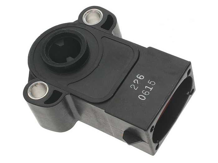
Ford Tps Sensor Wiring Wiring Library Throttle Position Sensor
THROTTLE POSITION SENSOR explanation for wiring diagram, troubleshooting and simplify tutorial Automotive electronics from schematics by Joseph 10.9K subscribers Subscribe Subscribed 141.

Throttle position sensor codes 2006 f150
Testing and troubleshooting the throttle position sensor (TPS) on your Ford or Lincoln car, pick up or SUV is an easy thing to do. You don't even need a scan tool to test it. A simple multimeter will suffice and in this article, I'll take you thru' the whole diagnostic process step by step.

Throttle Position Sensor Problems and Solutions Auto Quarterly
How Does The Throttle Position Sensor Work? Where To Buy The TPS And Save. TEST 1: Testing The TP Signal With A Multimeter. TEST 2: Making Sure The TPS Is Getting 5 Volts. TEST 3: Making Sure The TPS Is Getting Ground. The TPS Code Won't Go Away. More Ford 5.0L And 5.8L Tutorials.

2002 Ford Windstar Heater Hose Diagram Wiring Site Resource
The Ford (or Mercury) throttle position sensor is a simple three wire TPS. Below, you'll find out what each wire (circuit) does. All three circuits start and end at the PCM (Powertrain Control Module=Fuel Injection Computer) or vice-versa, depending on how you look at it. Circuit labeled 1 : Power Circuit. 5 Volts from the PCM. Circuit labeled 2 :
How Do You Know If a Throttle Position Sensor Is Bad? AxleAddict
6. MAF sensor contamination: A) install sensor in upper half of cross sectional area to minimize possibility of condensation coming in contact with the MAF sensor element. In other words, if a clock is superimposed on a cross section of the zip tube, the sensor should be installed somewhere equal to or above the 9:00 and 3:00 positions.
Ford Throttle Position Sensor Wiring Diagram Lorean Constantine
A TPS provides throttle opening angle information the engine management system. This is used for many aspects of engine control from use as the main load signal for fuel and ignition calculation, to detecting idle conditions, detecting when the engine is decelerating, and adding fuel and ignition corrections during rapid throttle opening.

2008 F250 5.4 Throttle Position Sensor Wiring Diagram
1. Examining the TPS Harness: The TPS harness, an ensemble of intricate wiring, is the unsung hero of the system. To ensure optimal performance, it is vital to inspect the connections within this harness. Check for any signs of wear, fraying, or corrosion that may impede the transmission of electronic signals.
Throttle position sensor problem?
The throttle position sensor (TPS) is a device on the engine that detects the position of the throttle plate. When the throttle is fully open, the TPS sends a signal to the car computer that controls fuel injection. It also sends a signal to the ECU when the throttle is closed, so it can adjust timing and fuel delivery accordingly.
THROTTLE POSITION SENSOR We Are Getting a Code Message of P2106...
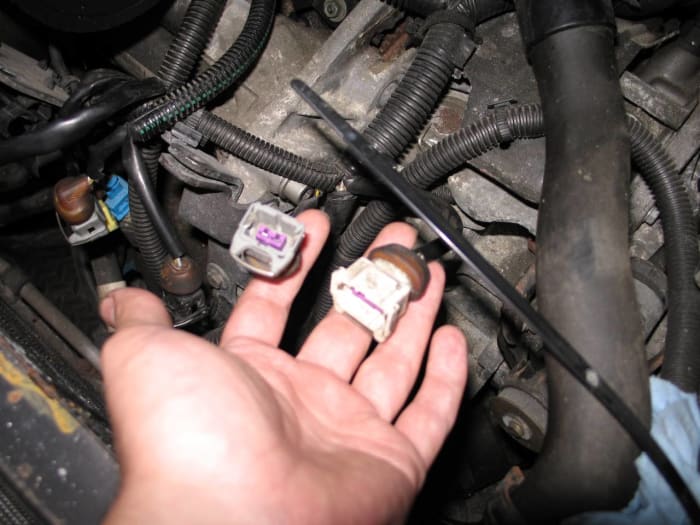
Ford Throttle Position Sensor Connections Ford has two different color codes for throttle position sensors and several different connectors and pin-outs.

Ford Throttle Position Sensor Wiring Diagram Wiring Diagram Schematic
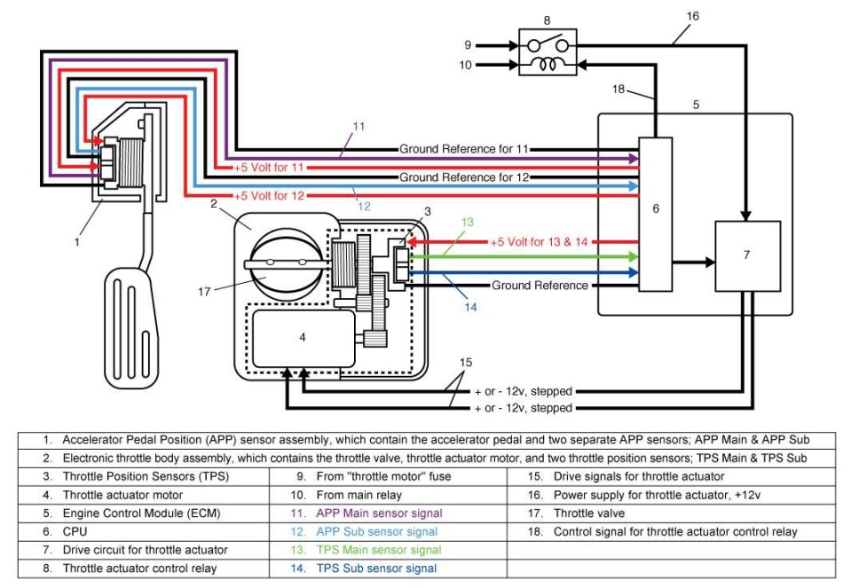
Ford Tech Tips V2 | N2 2020 5 Throttle Body and Throttle Pedal Diagnostics It's a hardware and software strategy delivering engine torque output via throttle angle. Based on driver intent, torque-based electronic throttle uses a throttle pedal position sensor. Gen II is a drive-by-wire system eliminating the idle air control system.

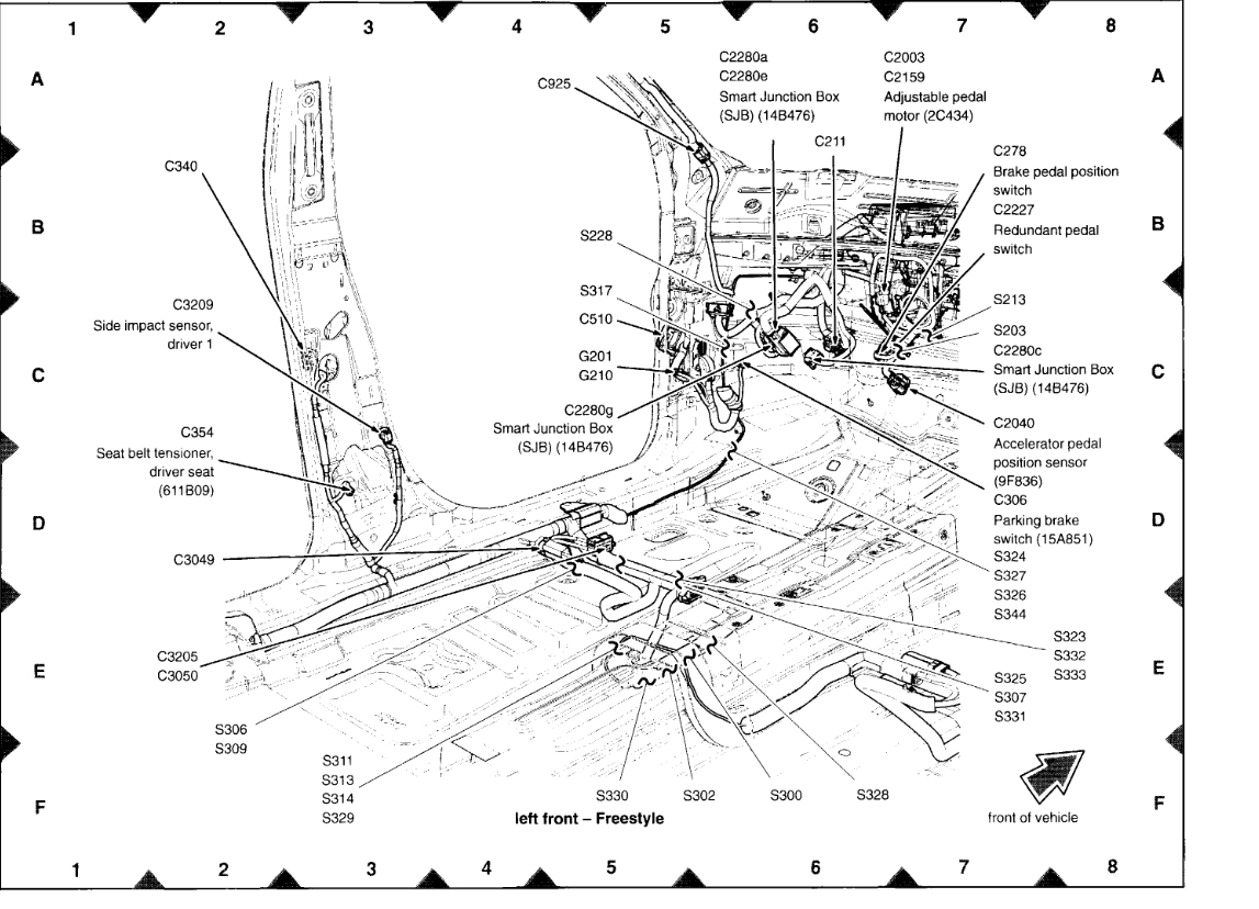
Where is the throttle position sensor located on a 2004 F250 Super Duty
Crankshaft position sensor (CKP) (located at the front of the engine next to crankshaft pulley) Cylinder Head Temp Sensor (CHT) (located under the cover at the front towards the front of vehicle) Coil on Plug Ignition coils (on top of cylinder head cover) Universal Heated Oxygen Sensor (HO2S11) (located in exhaust manifold at front of engine)

New Engine Camshaft Position Sensor Fits 12568715, 12571266, 12584079
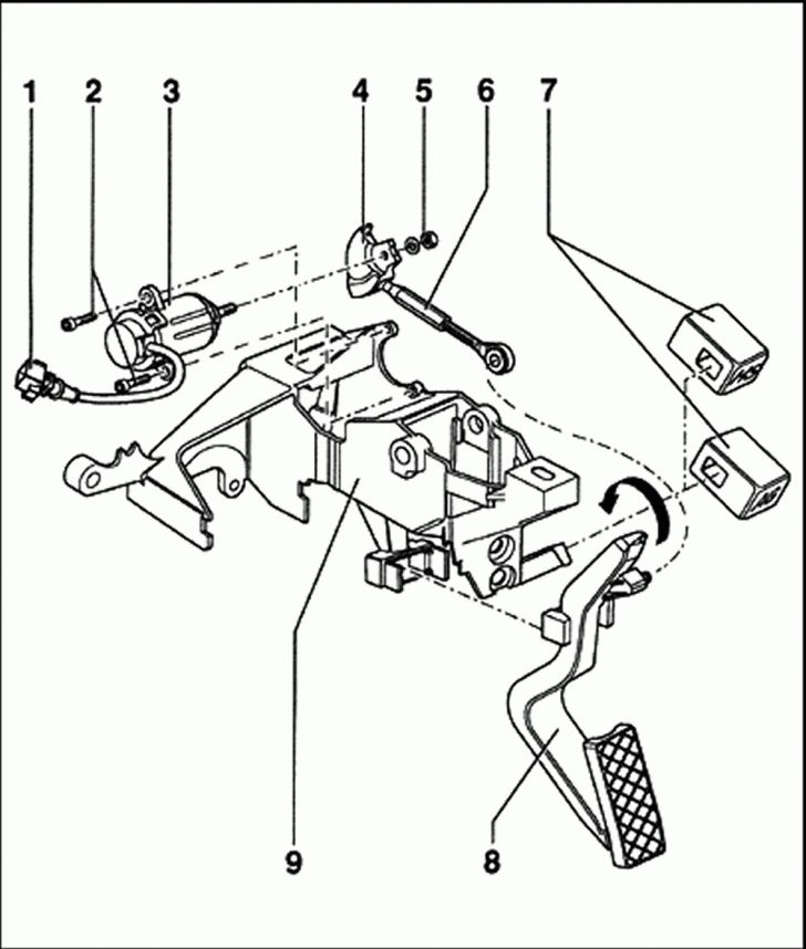
New throttle position sensor Step 1 - Remove the obstacles Remove the throttle body cover, then remove throttle body sensor, which is mounted on the front of your mantle fold. Then, take the accelerator cable off using a flat head screw driver by pressing under the part. Figure 1. Throttle Body Cover. Figure 2. Throttle Body Sensor. Figure 3.
Ford Throttle Position Sensor Autosport Labs
Once the throttle plate opens (like when you step on the accelerator pedal), the throttle position sensor reacts to the amount of throttle plate movement and creates and increasing voltage signal. At wide-open throttle (WOT), the TPS should output about 4.8 Volts DC.

8 Pin Throttle Position Sensor Wiring Diagram
The 4 wire throttle position sensor is an essential component in modern automotive engines.It measures the position of the throttle valve and provides this information to the engine control unit (ECU). This sensor helps the ECU determine the appropriate fuel-air mixture and ignition timing for optimal engine performance.The 4 wire throttle position sensor consists of four wires: a 5V reference.
Accelerator Pedal Position Sensor Wiring Diagram Printable Form
A Ford throttle position sensor (TPS) wiring diagram is a great way to understand how the TPS works. This type of sensor is used to monitor the position of the throttle in a vehicle engine. It is used to identify the exact position of the throttle when the accelerator pedal is pressed.
